Posted by Prahlad Parmar on May 23, 2016
The focus of the sheet metal industry has been on the automation of punching, shearing and nesting process for sheet metal parts and minimal focus was on the sheet metal bending operation. Appropriate representation of a sheet metal part with help of a 3D CAD model should provide adequate information to prepare a comprehensive production plan. The sheet metal design or the SolidWorks CAD model must be definite, and should signify one and precisely one part, may it be flat pattern of the final shape. At the same time the sheet metal design is required to be complete so as to ensure that all the information required for recognizing a correct part is present, including sheet metal tolerances.
A lot has been said about sheet metal fabrication, that it is mainly a subtractive process. However, there are several sheet metal tools or ways of using forming mechanisms to shape sheet metal without removing any material from it, at all. As an alternative, a given force is applied to change the geometry of the sheet metal. For executing this process, the force is required to be great enough to pressurize the sheet metal beyond its yield strength, but not to the extent that the sheet metal fractures of breaks.
Simple bending is where the sheet metal’s shape is changed at only one axis point, whereas complex parts are created by applying additional operations to the piece. Sheet metal bending is used to create V, U or channel shapes that are created with help of brakes. One can not only create sheet metal parts in SolidWorks, but even take assistance for the sheet metal bending process. It helps you to achieve the exact requirements and tight tolerances, the one that your customer’s sheet metal product expects.
The word “bending” itself is an indication that it is not simple. When you ought to bend something, it’s going to be a bit difficult. There are multiple kinds of bending and each has its advantages and disadvantages. The key difference between each type of sheet metal bending is characterized by the relationship between the thickness of the sheet metal material and the end tool position.
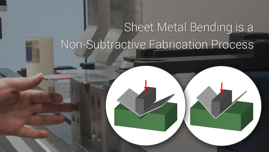
Air bending forms the sheet metal material by pressing a punch, upper or top die, into the material; forcing it into a bottom V-die, which is mounted on the press. The opening of the bottom die should be chosen adequately depending on the thickness and bend radius of the sheet metal material. One of the good thumb rules is 6 to 12 times the material thickness. The drawback here with Air bending is that it is not great when it comes to angular accuracy. However; it accommodates several materials, material thicknesses and bend angles without retooling.
Bottoming is where a piece of sheet metal is forced against the “V” opening in the bottom of the tool to create the “V” shape. In this case the punch presses the materials against the inner surface of the bottom die, while the angle of the bottom tool defines the bend angle. It is more accurate and has less spring back than air bending. A rule of thumb says that 8 times the material thickness will make a good bottom die opening. This bending technique involves greater forces which makes it all the more important to use the right kind of dies. It requires separate bottom dies and retooling for every bending angle as well as significantly more pressure.
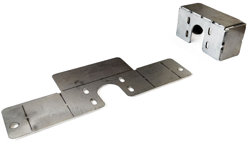
Slotting is the process where slots can be cut at the bending line to selectively weaken the material. Here you define the bend region and reduce the force that is required to bend a part out of sheet metal down, without using a brake press. This particular sheet metal bending technique is usually used to get custom metal enclosures and frames for small robotic projects and at times even for those large unloaded structures. But because it weakens the material, it’s a no-no for heavy load-bearing parts that rely on the structural integrity of the bend region.
There are various other sheet metal bending techniques as well including; Coining, Folding, Wiping, Three-Point Bending, Rotary Bending, Elastomer Bending, Roll Bending and Joggling.
Furniture manufacturers are no exception to the wide plethora of industries, seeking assistance from engineering service providers who are experts at SolidWorks. They help these furniture manufacturers with Sheet metal drafting & drawing using SolidWorks for their modeling projects of any household or Commercial Furniture products made of Sheet Metal or Tubular metal: Stainless Steel (SS), Aluminum, Brass, Copper, or Iron.
Building Products & Components Manufacturing industry is one of the prime consumers. Their several products including Metal Frames, Doors & Windows, Fire Suppression Equipment, HVAC need assistance from SolidWorks CAD models. Apart from these, the Structural Metal and Metal Plate work products or Metal Fabrications including Stairways, Ladders, Railings, Gratings, Strut Channels, Roofing (including copper), FAÇADE, etc. are consistently in need of mechanical design support services from SolidWorks vendors.
Last but not the least in the race is fabricated metal and alloy manufacturers, involved in Heavy Gauge Metal & Alloy Products, Components, and Equipments for Auto Ancillaries, Construction, Industrial, Agricultural, Transportation, Defense, etc.
So now that the basics of sheet metal bending are clear up to some extent, you can go ahead to build your own custom steel enclosures, robot frames or mounting brackets with help of a brake press or the slotting method. But, you would always need our assistance to put this entire sheet mental bending process in the right perspective, as we have successfully provided best Sheet metal drafting & drawing using SolidWorks, across UK, USA, Europe, Australia and Middle East.
Sources

About Author: Prahlad Parmar is an Engineering Specialist working at Mechanical 3D Modelling for the past 4 years. He caters critical engineering challenges with ease and performs exhaustive procedures to develop robust, well-engineered and high performance designs. He can always be found in the lab discussing, brainstorming and tweaking designs.
Mechanical 3D Modelling
Hi-Tech House, Gurukul,
Ahmedabad-380 052, Gujarat, INDIA.
Phone:
+91-794-000 3252